
by Holger Höltke on 09/20/2020
MM-Fiber Coupling Principles – Part 1
To couple laser light into or out of a multi-mode fiber, several optical coupling principles are commonly used in our industry. Over the next two articles, we compare the two most common one: the widely spread lens-prism-coupling and the direct or butt coupling.
Direct coupling / butt coupling
Direct or butt coupling denotes the alignment of the optical fiber direct in front of the active area of the laser or the photodiode without the use of any lens or prism within the optical path. The figure below depicts the direct coupling principle in a simplified manner.
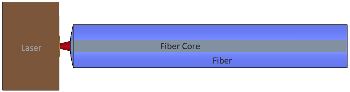
Simplified Direct Coupling Principle
Due to the astigmatism of edge emitting semiconductor laser, the brute-force approach of simply butting an
optical fiber almost against the laser diode allows usually for only about 10 to 20% coupling efficiency, or
a 7 to 10dB coupling loss.
However, due to the small aperture, relatively low beam divergence, and the circular beam profile, for
VCSELs butt coupling is an inexpensive alternative to the widely spread lens-prism-coupling.
Cleaved or cut multi-mode glass or polymer optical fibers will be inserted into some kind of fiber guiding
channels until the fiber tip almost reaches the VCSEL mesa.
At ideal conditions, the butt-coupling efficiency can reach up to 90%.
Next to the high coupling efficiency when used with VCSELs and photodiodes, direct coupling excels also in
its high tolerance to linear and angular alignment offset between the light source and the fiber as well as
the photo diode and the fiber.
This allows for highly cost-efficient, passive fiber coupling methodologies in fully automated assembly
lines.
Unfortunately, direct coupling exhibits also some significant drawbacks, which limit the applications for
this coupling principle.
First and foremost, the direct coupling suffers from its inherent data rate limitation.
Both ends of the fiber, the TX side, where light is coupled into the fiber, and the RX side, where light is
coupled onto the active area of the photodiode, contribute with different mechanisms to this data rate
limitation.
The main limiting parameter at the TX side is the beam divergence of the VCSEL, which usually exceeds the
numerical aperture (NA) of the fiber, leading to a mismatch between the electric field distribution of the
VCSEL beam and the waveguide modes of the fiber.
Dependent on the characteristics of the used VCSEL, passive fiber coupling methods are safely doable for
data rates of up to approx. 10 Gbps.
At the RX side, the fiber NA determines the emergent angle of the exiting light cone.
For a typical 50 micrometer fiber core connected to a standard 10 Gbps photodiode, after a few ten
micrometers, light is already so widely dispersed that it exceeds the active area of this photodiode.
Coupling losses will increase, which leads to a declining signal-to-noise ratio (SNR), which eventually
causes a higher bit error rate (BER).
This effect gets worse if photodiodes for higher data rates (e.g. 25 Gbps) are used. Usually these
photodiodes exhibit an active area that is even smaller than the fiber core, making it very hard to couple
sufficient light onto their active areas.
Another challenge for the direct coupling principle is the electrical connection to the VCSEL and the
photodiode bare die.
Usually, optical systems in active optical cables are requested to fit into small connector housings of a
few millimeters in height.
While VCSEL and the photodiode bare die emit or receive light along their Y-axis, light in the cable has to
travel along the X-axis. This requires turning the active optical components by 90°, in order to align their
optical axis with that of the fiber in the cable.
However, this imposes a bending of the electrical signals to and from these active optical components.
In the second article of this series we’ll look into the lens-prism-coupling and compare it to the direct or butt coupling. Click here to continue to second part!